Position in the Analog World

When working in modular synthesis systems, the most seemingly straightforward actions–say, positioning an image in a specific spot on the screen–can take a rather roundabout approach to get there. Folks coming from a more traditional digital workflow, this can be frustrating and illogical, but it also opens up lots of different avenues and approaches that the straightforward solution may skip over.
The Analog Approach
Image positioning in analog video is a pain mostly because analog video signals do not work in terms of an X-Y coordinate system. You'll have to remember that in analog video, individual horizontal lines are being spit out at a very fast rate which your eye interprets as a stable image. Let's take a simple square wave oscillator:

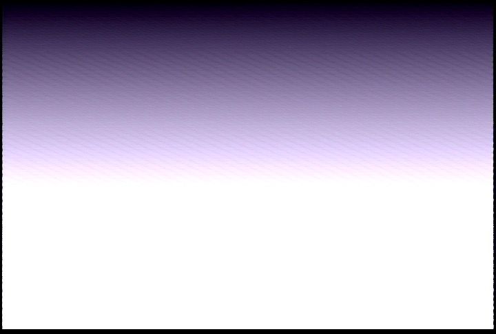
This waveform is alternating between 0V (black) and 1V (white). Now, imagine that this signal is a single horizontal line. Multiply it all the way down the screen and you'll get this:

Make sense?
In order to get X-Y addressing and positioning (as one would think of it in, say, Photoshop or After Effects, or even drawing on a piece of paper), you would need to know the contents of the entire frame ahead of time and then generate the output one line at a time. All of this happens extremely quickly, of course, but it requires a lot of continual calculations per frame, making this approach better suited to the digital domain.
Once you think about the hows and whys of what is taking place, you start to see the analog approach making more in-the-moment sense than the full-frame calculation.
The Power of Ramps
Okay, you get that, but you still want to do more traditional 2D movement (moving left, right, up, and down; rotating a shape) in the analog world. How do you do that?
There are a couple dedicated modules to handle this specific case. Some, like the LZX Memory Palace, use a digital frame buffer to grab an entire frame of information and then perform mathematical transforms on the frame to get it to do your bidding. Others, like the LZX Navigator and LZX Shapechanger take a more analog approach.
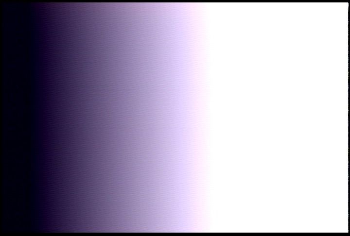
The main inputs on the Navigator and Shapechanger are Horizontal and Vertical ramps. These are gradients that are locked to the video clock for horizontal and vertical refresh rates. They look like this:


While being very useful for gradient shapes and modulators in your video work, they are notably useful here because they represent a kind of addressing system relative to the video clock. Instead of having to deal with entire frame calculations, all you need to do is manipulate the ramps and use the manipulated ramps as your modulation source to get a manipulated output.
Check out the Navigator 3 Patches video for an idea of how this can be used in practice:
An Exercise For the Reader
Using horizontal and vertical ramps, you can also approximate X-Y grid positioning. Let's say you had a $20 Arduino. Using only two of the analog input pins and one of the digital output pins, you can create a hard key generator.
Here's some pseudocode:
Loop through the vertical ramp input values
    Loop through the horizontal ramp input values
        Perform some logic based on the combined H/V values and output it to the digital pin
    End Loop
End Loop
We can take this further. Let's make a quadrilateral key generator. Quadrilateral being the accurate term here. Remember, ramps are relative to the video clock, so on a 4:3 output, you will get a 4:3 square-ish key, on a 16:9 output, you will get a 16:9 key.
The pseudocode would look something like this:
Loop through the vertical ramp input values
    Loop through the horizontal ramp input values
        If the horizontal value and the vertical value is > .25V and < .75V, output a 1 to the digital pin
        Else, output a 0 to the digital pin
    End Loop
End Loop
This code is tracking both the horizontal and vertical position using the ramps. If the voltage for either of the ramps fits within the voltage range, it will output 1V (white), otherwise, it outputs 0V (black), just like the square wave example above.
This simple concept can be easily expanded: attach two potentiometers to two more analog pins and use them as your .25V and .75V values. Now you can squash, stretch, and reposition your quadrilateral. Next, add CV control. Experiment with using an analog out (soft key) instead of a digital out (hard key). Manipulate your ramps by mixing an LFO prior to input and now you're warping the key. And you're off to the races.
Low-Rent Rotation
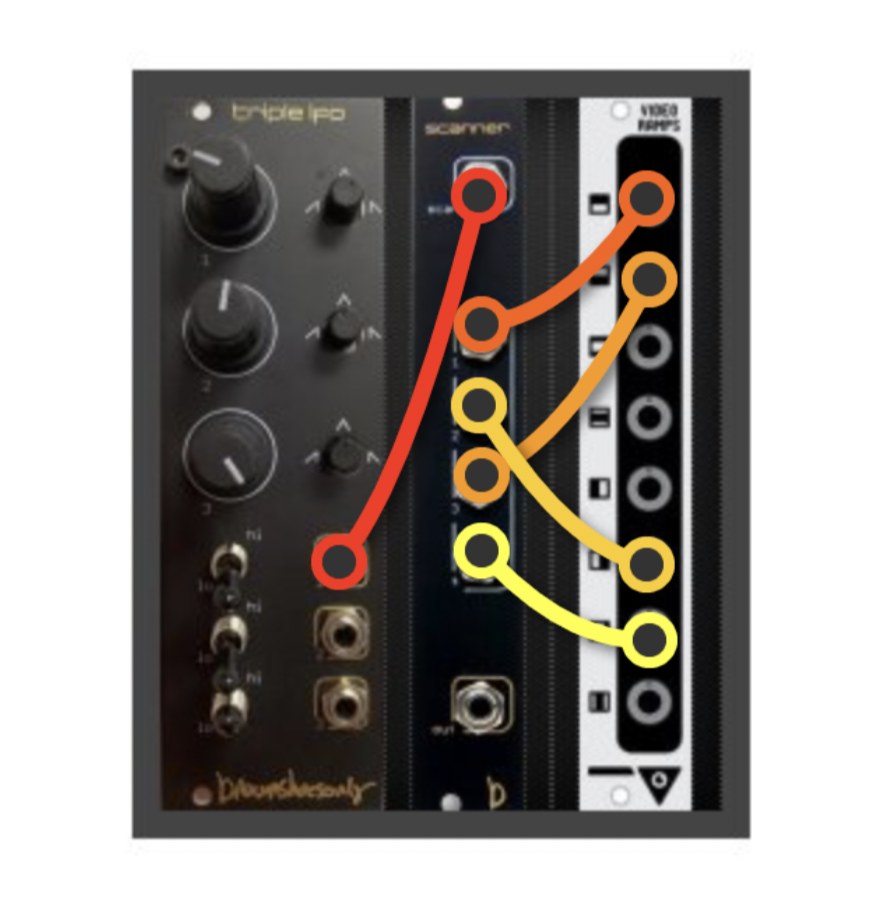
The entire post up to this point was a long-winded way to introduce a favorite recent patch of mine: low-rent rotation. It takes three modules: a LZX Ramps, a BSO Scanner, and an LFO.
The Scanner takes four inputs and maps them along a Scan CV control, where 0V sends the first input to the output, and 1V sends the last input to the output. Along the voltage spectrum, the inputs are mixed linearly at the output.
Now, if we feed four ramps in an alternating horizontal/vertical manner, the output will appear to move the gradient around as the ramps crossfade.
Patch:

And it looks like this:

Neat, huh? You can use the resulting signal on its own (I often throw it into a Staircase or a key generator to give it more of a shape), but you can also use it as a modulation source.
One caveat of this approach: notice the forward rotation and then the backward rotation? That's because the scanner does not loop around to the first input after the fourth input. I used a triangle LFO as a modulator, so it went from inputs 1 to 4 on the rise of the triangle, and then went from 4 to 1 on the fall of the triangle. It's not terrible, but you will not get continuous motion from this approach. If anything, it's an excuse to play with a complex envelope generator like the Doepfer A-143-1 to do video scratching rotation effects.
Here are some recent patches of mine that use this technique: